In September 2025, a fire inside a South Korean data centre forced nearly 200 firefighters to work for roughly 10 hours before they could bring it under control. The source was a battery explosion, and the fallout was immediate: more than 600 online government services went dark while the building burned.
That incident raises a question that procurement and infrastructure teams increasingly cannot avoid. If the battery room is where the fire starts, how do you actually verify that a battery system will contain it rather than let it spread?
The answer has sharpened recently. On 13 March 2026, UL Standards & Engagement published the sixth edition of UL 9540A, the standard that governs installation-level battery fire testing, just as the AI build-out is cramming denser lithium-ion systems into tighter data centre footprints. These two trends are colliding, and they make battery fire certification newly consequential for anyone writing a cheque for infrastructure.
Here is what the test data actually show, and what they mean for anyone specifying or procuring UPS battery systems in 2026.
Why battery fires in data centres have become a board-level problem
This is not a story about one unlucky building. It is a pattern.
According to Siemens’ technical document on emergency power supply fire protection, updated 29 August 2025, roughly 10% of data centre fire incidents involve uninterruptible power supply (UPS) equipment, the hardware that keeps servers running when mains power drops. That figure spans UPS gear broadly, including batteries and power electronics, rather than isolating lithium-ion thermal runaway alone.
The NFPA Journal put the trend bluntly in its February 2026 coverage.
“Nearly every notable fire event in data centers in recent years has involved lithium-ion batteries in some way.”
The documented incidents back that up. The South Korean fire of September 2025 halted hundreds of government services for most of a day. In 2021, a French data centre fire destroyed an entire building and roughly 30,000 servers, with batteries involved. Not every case is clean, though. At a Hillsboro facility, an event first blamed on batteries was later traced by Digital Realty to a 250 kVA power cabinet and confirmed as an electrical fault, a reminder that misclassification muddies the incident data.
What makes lithium-ion UPS batteries categorically different from the older lead-acid systems they replaced comes down to a handful of failure modes:
- Thermal runaway: a self-feeding temperature spike in a cell that can cascade to neighbouring cells and modules.
- Off-gassing and deflagration: flammable gases released during failure can ignite and cause a subsonic combustion event, generating overpressure in a confined battery room.
- Vertical flame propagation: heat rises, so fire spreads buoyantly up through stacked, rack-mounted modules faster than it moves sideways.
- UPS cabinet electrical faults: power electronics, capacitors, and wiring offer a separate ignition path distinct from the batteries themselves.
Here is why this matters to you if you specify or finance this infrastructure. AI workloads are pushing energy density up, squeezing cabinets closer together, and shrinking the separation distances that once bought time during a fire. The evaluation criteria you used for lead-acid UPS systems no longer cover the risk you are actually carrying.
The push toward factory-integrated platforms is one response to the same density problem that makes fire containment so consequential: as data centre battery rooms shrink and pack more energy into less space, the margin for thermal runaway to stay contained narrows sharply.
When big ASX news breaks, our subscribers know first
What UL 9540A actually tests, and why cell-level results do not tell the whole story
The logic of UL 9540A is a ladder, and each rung answers a question the one below it cannot.
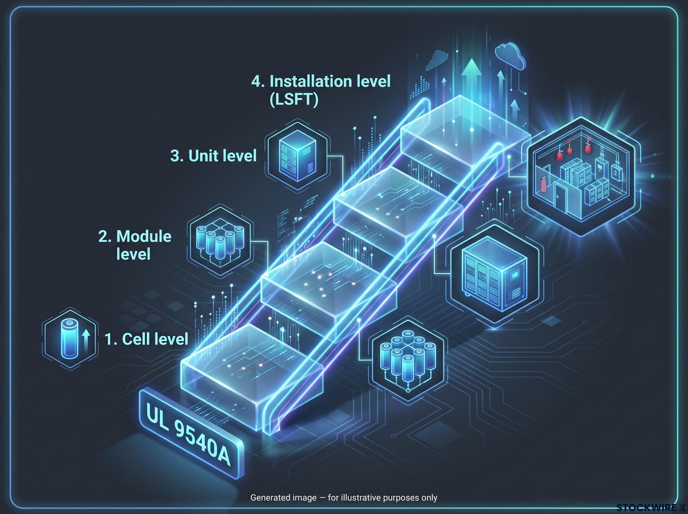
The sixth edition evaluates a battery system at four sequential levels:
- Cell level: does an individual cell undergo thermal runaway, and how does it behave when it does?
- Module level: when cells are grouped into a module, does failure propagate between them?
- Unit level: how does a complete unit, with its enclosure and internal structure, respond?
- Installation level: the large-scale fire test (LSFT), which observes how a full installation behaves in a realistic building environment.
Here is the part worth internalising. A cell test tells you whether a cell can fail catastrophically. It tells you nothing about whether a fully assembled system, installed in a room with real ventilation, enclosure geometry, and suppression plumbing, will contain that failure. Only the installation-level test answers that.
The standard is explicit about its own purpose. It generates data to determine required separation distances between units and the fire and explosion protection needed for installations compliant with NFPA 855, the standard for stationary energy storage installation. The sixth edition’s large-scale fire test aligns directly with NFPA 855-2026 Annex G.11. UL 9540A is a data-generating test method, not a stand-alone design approval.
That data feeds into a wider compliance stack.
| Standard | Scope | Role in installation approval |
|---|---|---|
| UL 9540A | Thermal runaway fire propagation test method | Generates hazard data; does not approve on its own |
| UL 9540 | Energy storage systems and equipment | Product listing the LSFT data feeds into |
| NFPA 855 | Installation of stationary energy storage | Sets installation requirements informed by LSFT results |
| NFPA 70 | National Electrical Code | Governs electrical compliance of the installation |
A system that has cleared cell and module testing but never completed the installation-level LSFT simply cannot give you data on the questions that govern how your building and its suppression infrastructure will respond to a thermal runaway event. A cell-level result is not a system-level result.
What the large-scale fire test actually evaluates
The LSFT simulates a specific scenario: thermal runaway triggered in one initiating module, arranged in a realistic installation layout, with the fire monitored to see whether it spreads to adjacent units and whether the building’s suppression system activates.
The sixth edition also assumes a post-deflagration condition and requires vertical initiation across full module groupings, capturing the buoyancy-driven flame spread and heat-flux escalation that rack configurations produce. Active suppression inside the enclosure of origin is switched off during the test, forcing the system to prove containment on its own merits.
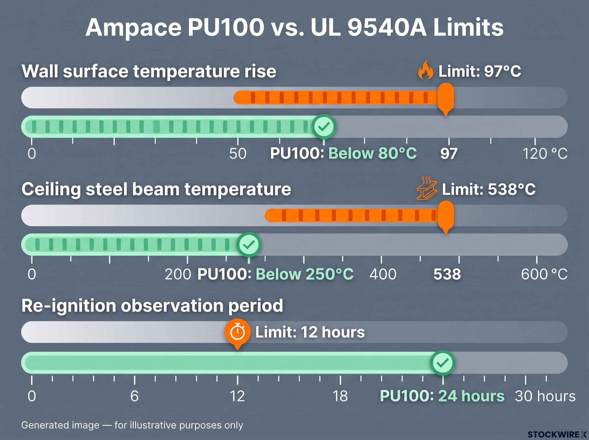
Three numeric thresholds define a passing result under the sixth edition: a wall surface temperature rise capped at 97°C, a ceiling steel beam temperature capped at 538°C, and a re-ignition observation period of at least 12 hours. These specific figures are cited in Dr. Drew Feng’s 2026 conference presentation on the standard and are not independently confirmed in freely accessible web summaries of UL 9540A.
The Ampace PU100 test: what the numbers show at extreme configuration limits
Before the results, look at the conditions, because the severity of the setup is the point.
Ampace tested its PU100 UPS battery system under an arrangement built to replicate a dense data centre deployment, not a comfortable laboratory margin.
| Parameter | Value |
|---|---|
| Ceiling height | 3 metres |
| Cabinet side-by-side clearance | 0 mm |
| Back-to-back cabinet spacing | 20 mm |
| Face-to-face cabinet clearance | 850 mm |
| State of charge during testing | 100% |
Zero side clearance and a full 100% state of charge represent a harder scenario than many real deployments will ever impose. Thermal runaway was triggered in the initiating module using heaters, then ignited to sustain combustion.
The results, as reported by Ampace, unfolded in sequence. Thermal runaway stayed contained to the initiating module and never reached adjacent cabinets. The sprinklers never activated. Combustion self-extinguished after roughly 40 minutes with no intervention. No re-ignition occurred across a 24-hour monitoring window, and no burning debris exited the cabinet.
Measured against the three sixth-edition thresholds, the margins were wide.
| Criterion | UL 9540A sixth-edition limit | PU100 result |
|---|---|---|
| Wall surface temperature rise | 97°C or below | Below 80°C |
| Ceiling steel beam temperature | 538°C or below | Below 250°C |
| Re-ignition observation period | 12 hours minimum | 24 hours, no re-ignition |
The adjacent modules did more than survive. They kept working.
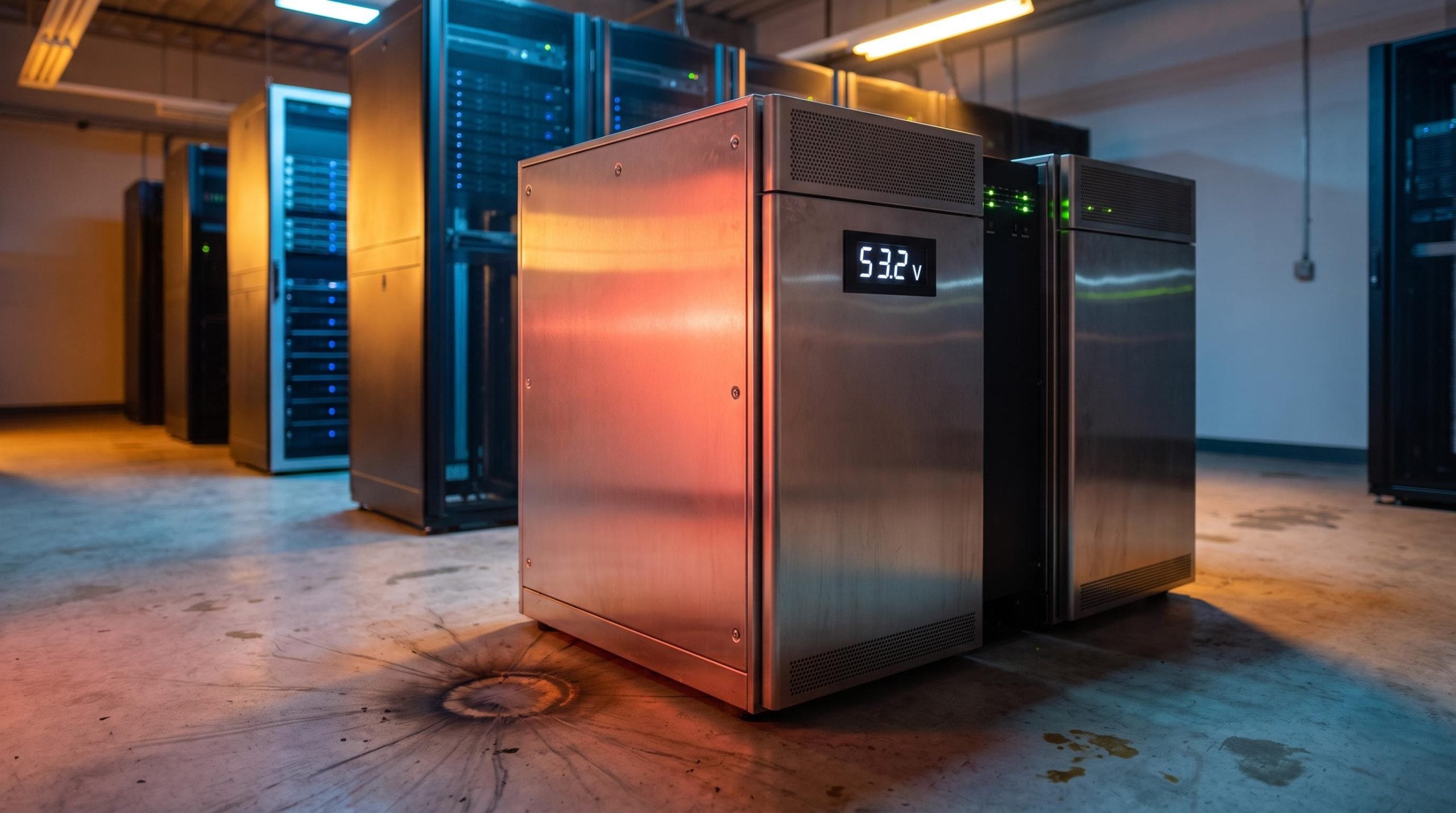
Adjacent module integrity Modules next to the initiating unit showed no thermal runaway and maintained normal voltage output of 53.2 V after the test, an indicator of functional integrity rather than mere survival.
For you as an evaluator, the headroom is the story. A wall temperature below 80°C against a 97°C limit, achieved at 100% charge with cabinets touching, gives you a quantitative basis for judging the system’s margin under conditions more punishing than most installations present.
One caveat matters. These are company-reported results presented at a company-affiliated conference, and no independent third-party verification of the specific numeric outcomes has been identified.
The design logic behind passive containment and why it matters more than suppression systems
Those numbers were not luck. They were the output of a specific engineering philosophy that the sixth edition was written to expose.
UL 9540A sixth edition embeds a passive-first safety philosophy. Active HVAC and suppression within the enclosure of origin are disabled during installation-level testing precisely because the standard wants proof that containment works through inherent design, not through mitigation that might fail or might simply be absent on the day.
The PU100’s design features are what the test results reflect:
- All-metal module and cabinet enclosures.
- Ceramic thermal insulation inside the modules.
- Thermal barriers at the high-voltage box level.
- Thermal barriers at the cabinet level.
The distinction here carries real weight for you. A system that passes because its suppression system intervened and a system that passes because the fire never propagated represent two fundamentally different risk profiles the day a suppression system fails.
What sprinkler inactivity during testing actually indicates
The sprinklers staying off throughout the PU100 test is not a convenient footnote. It is evidence.
It means the heat flux the fire generated never reached the suppression system’s activation threshold, which is itself a direct measure of how well the fire was contained within the initiating cabinet. Contrast that with a test where sprinklers activate and knock the fire down: in that case, the passing outcome depends on the suppression system working correctly. The PU100 result did not.
So you can ask any vendor a precise question. Does your LSFT result reflect containment by design, or containment by suppression? The answer rewrites the residual risk of the installation.
The credentials behind the presentation add context. Dr. Drew Feng, who presented the findings, is credited by Ampace with contributing to 19 UL standards, including UL 9540 and UL 9540A, and serving as a voting member on UL technical committees. Independent corroboration of these specific credentials has not been identified.
What procurement and infrastructure teams should look for when evaluating battery fire safety claims
Having followed the logic this far, you can turn it into a checklist. When a vendor puts fire safety credentials in front of you, five questions separate a meaningful claim from a reassuring one:
- Which test tier do your results correspond to? Cell, module, unit, or installation-level LSFT. Only the fourth answers the system-level question.
- What were the installation configuration parameters? State of charge, cabinet clearances, and ceiling height. A test at 50% charge with generous spacing is far gentler than one at 100% charge with zero side clearance.
- Were active suppression systems disabled during testing? The passive-first criterion tells you whether containment was proven by design.
- What were the specific numeric results against each threshold? Wall temperature against 97°C, ceiling beam against 538°C, re-ignition period against the 12-hour minimum.
- Which elements of the broader compliance stack does the product satisfy? UL 9540 listing, NFPA 855, NFPA 70, and applicable local codes.
Those configuration parameters deserve particular attention, because they decide how much the headline result is worth. A generous separation distance and a half-charged battery produce a less demanding scenario, and a pass under easy conditions tells you less than a pass under worst-case ones.
Keep the LSFT in proportion, too. It is one input into a wider framework, not a stand-alone guarantee. The data feeds installation design decisions rather than replacing them.
As of October 2026, Ampace is the only named UPS battery manufacturer identified in available sources as having publicly presented installation-level LSFT results aligned with the sixth-edition criteria.
The real limitation of silence The absence of published installation-level LSFT results from a vendor does not mean their product is unsafe. It does mean you lack quantitative data on the most consequential question of all: how the system behaves as an installed unit, in a real building, under worst-case conditions.
This article is for informational purposes only and should not be considered financial advice. Investors should conduct their own research and consult with financial professionals before making investment decisions.
What the sixth-edition standard and the 2026 test results signal about where battery safety is heading
Step back and the shape of the shift becomes clear. This is not a one-off certification for one product. It is a structural change in how battery fire safety will be evaluated and competed on.
The publication of the sixth edition on 13 March 2026, and its alignment with NFPA 855-2026 Annex G.11, formalises a methodology the industry had already been drifting toward. Installation-level assessment is now the expected benchmark, not an optional extra. Three directional signals stand out:
- Installation-level testing is now the formalised benchmark, embedded in the standard rather than offered as an add-on.
- The passive-first philosophy marks the regulatory direction of travel, demanding proof of inherent containment over reliance on suppression.
- Competitive differentiation is moving toward disclosed, quantitative LSFT results.
For anyone planning data centre battery procurement over the next 12-24 months, the practical consequence is direct. “UL-listed” without installation-level LSFT data will increasingly read as an incomplete answer to the fire safety question, so building the right criteria into your procurement specifications now puts you ahead of the curve.
Battery fire safety and grid interconnection constraints are converging as the two technical bottlenecks that determine whether a new AI data centre facility can come online at all, and on what timeline.
Why disclosed LSFT results are becoming a competitive differentiator
In a market where installation-level testing is formalised in the standard, a vendor who publicly discloses quantitative results against the sixth-edition thresholds hands you an evaluation basis that a vendor without disclosed results simply cannot match.
That dynamic holds regardless of whether undisclosed results exist somewhere internally. Your position as a buyer is set by the data available to you, not by what might sit in a vendor’s files. On that measure, Ampace’s disclosure is notable precisely because no comparable disclosure from other named UPS or stationary battery manufacturers has been identified in available sources as of October 2026. Absence of evidence is not evidence of absence, but it does shape who you can evaluate with confidence today.